IMUTag
IMUTag is the high-rate end of the family. Where a BitTag spends one bit per second, an IMUTag resolves individual wingbeats — and fills its memory in a day doing it. The board documented here is imutag-smps: the revision with a switching regulator and NAND flash.
The board
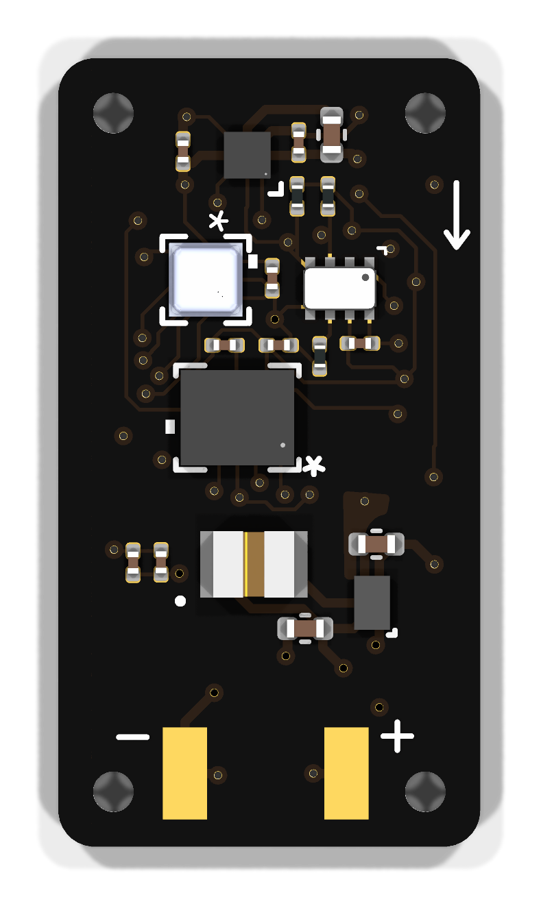
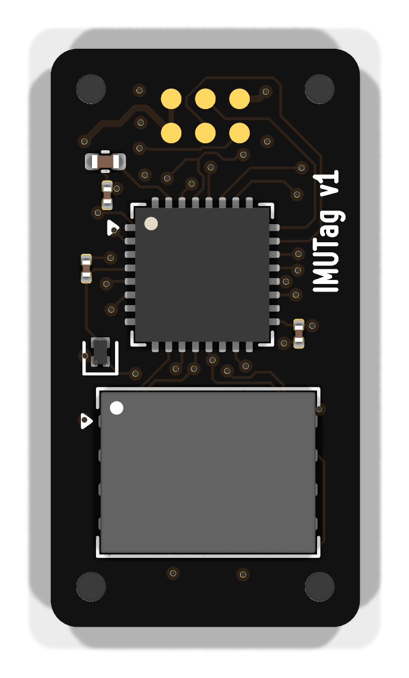
The inductor beside the buck converter is the visible sign of the only switching supply in the family. These are rendered from the KiCad layout by kicad-cli; see
Board Designs for how they are regenerated.
Block diagram
flowchart LR
  subgraph TAG[imutag-smps]
    direction LR
    subgraph ON["Always on (+1V8)"]
      direction TB
      RTC["RV-3028-C8<br/>RTC"]
      MCU["STM32U375KGU6<br/>processor"]
      IMU["LSM6DSV<br/>accel + gyro"]
      MAG["BMM350<br/>magnetometer"]
      PRS["BMP581<br/>pressure"]
      NAND["GD5F2GM7RE<br/>NAND flash"]
      RTC --- MCU
      MCU --- IMU
      MCU --- MAG
      MCU --- PRS
      MCU --- NAND
    end
    subgraph PWR[Power]
      BAT["12 mAh LiPo cell"]
      BUCK["TPS62840 buck<br/>+ 2.2 µH"]
      BAT --- BUCK
    end
    IF["Interface<br/>SWD + pogo pads"]
  end
  ON --- PWR
  ON --- IF
There is no switched section, and that is a deliberate result rather than an
omission. An earlier revision gated the NAND flash behind a TPS22916 load
switch on FLASH_PWR. Power measurements showed the benefit was negligible, so
in September 2026 the load switch, its two capacitors and both of its nets were
removed and the NAND was wired straight to +1V8. The trade is that the NAND's
standby current is now drawn continuously — measured, accepted, and worth
re-measuring rather than re-assuming if the deployment duty cycle ever changes
materially.
Major components
| Role | Part | Notes |
|---|---|---|
| Processor | STM32U375KGU6 | The only board in the family not on an STM32L4 |
| RTC | RV-3028-C8 | 32.768 kHz, 1 ppm |
| Sensor | LSM6DSV | 6-axis inertial measurement: acceleration and rotation rate |
| Sensor | BMM350 | 3-axis magnetometer |
| Sensor | BMP581 | Barometric pressure and temperature |
| Memory | GD5F2GM7REYIGR | NAND flash — far larger than the serial flash the other tags carry |
| Power | TPS62840YBGR + 2.2 µH | Step-down switching converter producing +1V8 |
| Battery | 12 mAh LiPo | Specific cell not yet settled |
This is the only tag with a switching converter. Every other board in the family runs its parts directly from the cell through a Schottky diode. At IMUTag's sampling rates the processor and sensors draw enough that a buck converter's efficiency earns its complexity — and the whole board then sits on a single regulated 1.8 V rail rather than on a battery voltage that sags as the cell drains.
The converter is also what lets this board use a different cell. Every other tag is tied to a 3 V coin cell because its parts sit directly on the rail; put a 4.2 V LiPo on one and you are at the absolute maximum of the processor. Here the TPS62840 steps whatever the cell gives down to a regulated 1.8 V, so a 12 mAh LiPo is usable — more capacity than a coin cell, and a rail that stays at 1.8 V rather than sagging as the cell drains. The specific cell is not yet settled.
Using the YBG package has one consequence worth knowing: it has no MODE pin, so forced-PWM operation is not available on this board.
What it records
Acceleration, rotation rate, magnetic field, pressure and temperature, at sampling rates from 100 Hz to 1600 Hz. At those rates the question stops being "was the bird active" and becomes "how did it move" — wingbeat by wingbeat, including the orientation and altitude context around each flight.
The cost is endurance. An IMUTag records continuously for hours rather than months, and spends the rest of its deployment armed and waiting for a trigger. The IMUTag overview on the software site carries the current figures for both.
Power
Measured on firmware fw-v0.6 at 3.6932 V. This board regulates with
an SMPS, so every figure scales with supply voltage — unlike the coin-cell
tags, whose rail follows the cell.
| State | Current |
|---|---|
IDLE |
6.43 µA |
RUNNING at 400 Hz |
665 µA |
FINISHED |
6.43 µA |
Across sample rates, on a 12 mAh cell with the 2 Gbit NAND:
| Rate | Running | Battery limit | Storage limit | Usable | Binds on |
|---|---|---|---|---|---|
| 100 Hz | 539 µA | 22.3 h | 54.6 h | 22.3 h | battery |
| 200 Hz | 580 µA | 20.7 h | 27.3 h | 20.7 h | battery |
| 400 Hz | 662 µA | 18.1 h | 13.7 h | 13.7 h | storage |
| 800 Hz | 827 µA | 14.5 h | 6.8 h | 6.8 h | storage |
| 1600 Hz | 1003 µA | 12.0 h | 3.4 h | 3.4 h | storage |
Above 200 Hz the flash fills before the battery empties, crossing over near 300 Hz. A bigger cell buys nothing at 400 Hz and up.
Idle shelf life is about 74 days on a 12 mAh cell — the conservative end of an unresolved split, where seventeen readings fall into two populations near 6.7 and 5.5 µA, separating 74 days from 91.
IMUTag draws three orders of magnitude more than the coin-cell tags and alone decides whether a deployment makes its battery life.
Full log: IMUTag power and runtime.
Design files
Design directory on GitHub Schematic (PDF) Design review
The review is the most thorough in the repository: two rounds covering the
switching converter and its loop layout, the magnetometer noise and offset
budget, the full STM32U375 pin map including the SPI1 collisions, and the
reasoning behind removing the load switch. An earlier non-SMPS revision is in the
repository under BoardDesigns/Tags/imutag.