CompassTag
CompassTag adds a magnetometer, which makes heading a recoverable quantity rather than an inferred one. It is also the first board in the family to carry a second voltage rail, because the magnetometer it uses will not run at battery voltage.
The board
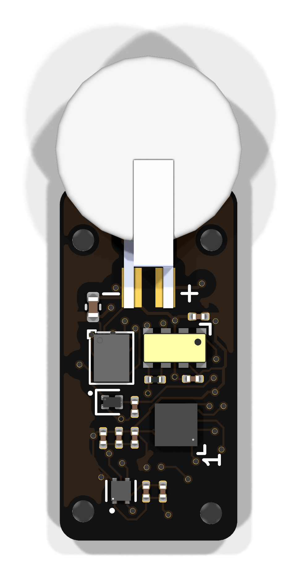
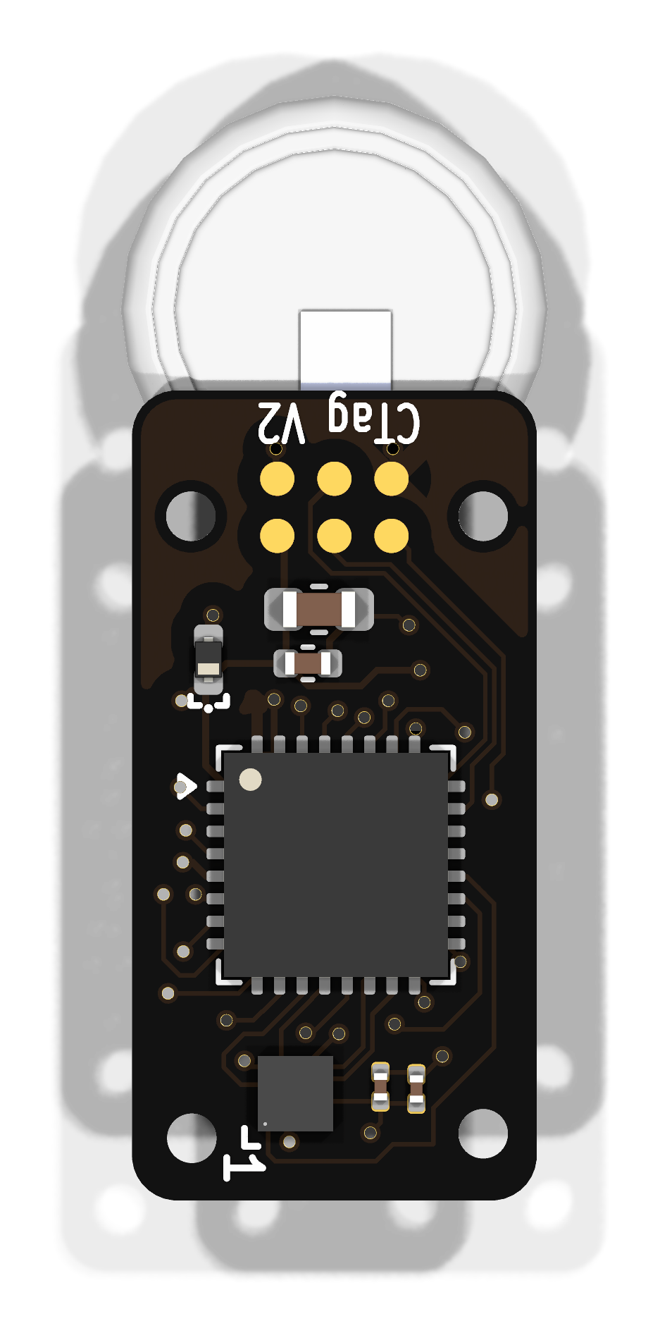
Two rails share this board: the magnetometer and its 1.8 V LDO against everything else on +2V5. These are rendered from the KiCad layout by kicad-cli; see
Board Designs for how they are regenerated.
Block diagram
flowchart LR
  subgraph TAG[CompassTag]
    direction LR
    subgraph SW["Switched (+1V8)"]
      MAG["AK09940A<br/>magnetometer"]
      LDO["TPS7A0218<br/>1.8 V LDO"]
      LDO --- MAG
    end
    subgraph ON["Always on (+2V5)"]
      direction TB
      RTC["RV-3028-C7<br/>RTC"]
      MCU["STM32L432KCU6<br/>processor"]
      ACC["LIS2DU12<br/>accelerometer"]
      FLASH["AT25XE321D<br/>4 MB serial flash"]
      RTC --- MCU
      MCU --- ACC
      MCU --- FLASH
    end
    subgraph PWR[Power]
      BAT["MS621FE-FL11E or<br/>MS920SE-FL27E coin cell"]
    end
    IF["Interface<br/>SWD + pogo pads"]
    SW --- ON
  end
  ON --- PWR
  ON --- IF
Major components
| Role | Part | Domain | Notes |
|---|---|---|---|
| Processor | STM32L432KCU6 | Always on, +2V5 | |
| RTC | RV-3028-C7 | Always on, +2V5 | 32.768 kHz, 1 ppm |
| Sensor | LIS2DU12 | Always on, +2V5 | 3-axis accelerometer |
| Sensor | AK09940A | Switched, +1V8 | 3-axis magnetometer |
| Regulator | TPS7A0218 | — | 1.8 V LDO serving only the magnetometer |
| Memory | AT25XE321D-UUN | Always on, +2V5 | 4 MB serial flash |
| Battery | MS621FE-FL11E or MS920SE-FL27E | — | 5.5 mAh / 230 mg, or 11 mAh / 450 mg |
The magnetometer has a rail of its own. The AK09940A runs at 1.8 V, so it
cannot share the +2V5 rail the rest of the board uses. The TPS7A0218 LDO
supplies it, and that LDO's enable pin is wired to processor pin PA9 on the net
AK_PWR. Switching the magnetometer off therefore switches off its regulator
too — the entire 1.8 V domain collapses, rather than the sensor idling on a live
rail. That is why the LDO is drawn inside the switched section rather than
alongside the battery.
The accelerometer stays powered. It is a low quiescent current part and it is what the processor watches to decide when anything interesting is happening.
Two firmware contracts come with the switched rail
The magnetometer's bus lines are driven from the +2V5 domain. While the 1.8 V
rail is off, driving AK_CK, AK_MOSI or AK_CS high risks back-powering
the sensor through its protection diodes, so those pins want to be high-Z or
pulled low whenever the domain is down. Separately, AK_RSTN should be held
low while the rail is off or still settling.
What it records
Three-axis acceleration and three-axis magnetic field. Together these give orientation and heading: the accelerometer establishes which way is down, and the magnetometer gives a bearing relative to it. The design intent is roughly 10 µA typical current, under 1 mA while actively operating, and about 10 mA at the peak of a flash write.
Power
Measured on firmware fw-v0.6 at 2.4960 V from an unregulated 2.5 V
cell, at the shipped 30 s compass period, in a 19.5 °C room.
| State | Current |
|---|---|
IDLE |
0.21 µA |
RUNNING, 30 s period |
1.95 µA |
FINISHED |
0.21 µA |
On the cell alone, roughly 120 days recording on a 5.5 mAh cell and 240 days on 11 mAh.
CompassTag runs several times harder than the other coin-cell tags — 1.95 µA against PresTag's 0.39 and UIUC Tag's 0.56. The magnetometer on the switched rail is why, and it makes the sample period a deployment-planning decision here rather than a detail.
Idle tracks room temperature: about 9% for 3.5 °C, while running stays flat to about 1%. Running is dominated by active work, idle by leakage.
Full log: CompassTag power results.
Design files
Design directory on GitHub Schematic (PDF) KiCad analysis
The analysis document carries the full processor pin map with a recommended reset and sleep state for every pin, which is the most useful thing in it if you are writing firmware for this board.