tagbase-lipo-v1
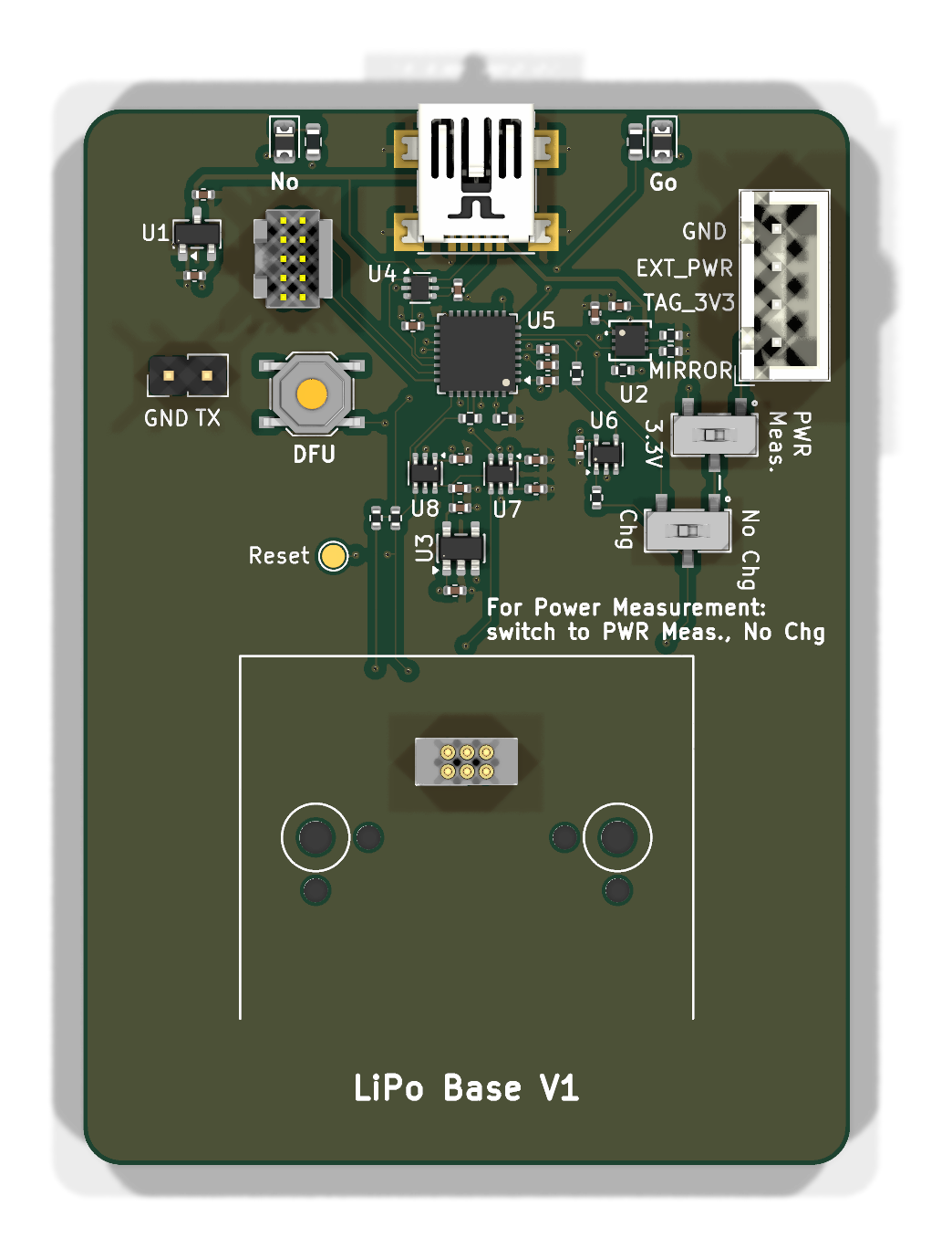
A tag base for LiPo-powered tags. Where the coin-cell bases fake a charger with a resistor, this board carries a real one — and it is the first of the bases to hand the supply over to an external instrument with a mechanical switch rather than an analog one.
Block diagram
flowchart TB
  subgraph IF["External interface"]
    direction LR
    MCU["STM32L432KB<br/>ST-LINK emulation"]
    REG["XC6206P332MR<br/>3.3 V"]
    USB["USB Mini-B (J104)"]
    SWD["SWD header (J102)"]
    ESD["USBLC6-2P6<br/>ESD protection"]
  end
  subgraph PWR["Power and measurement"]
    direction LR
    CHG["XC6808A4C28R-G<br/>LiPo charger"]
    REG2["AP2112K-1.8"]
    SHIFT["2 × SN74LVC1T45<br/>level shifters"]
    AMP["TLV9001<br/>op-amp"]
    SWCH["2 × SPDT slide switch<br/>supply changeover"]
  end
  subgraph TGT["Target interface"]
    POGO["6-pin pogo connector (J101)<br/>6pin_tagpoints_double_screws"]
  end
  IF --- PWR
  PWR --- TGT
Major components
| Role | Part | Notes |
|---|---|---|
| Programming processor | STM32L432KB | |
| Charger | XC6808A4C28R-G | A real LiPo charger, not a resistor |
| Regulators | XC6206P332MR, AP2112K-1.8 | 3.3 V and 1.8 V |
| Level shifters | SN74LVC1T45DCK ×2 | Between the 3.3 V interface and a 1.8 V target |
| Measurement | TLV9001IDCKR | |
| ESD | USBLC6-2P6 | On the USB port |
| Supply changeover | SW_SPDT ×2 | Mechanical, for handing the rail to a Joulescope |
| Target connector | 6pin_tagpoints_double_screws |
Pogo pins, with screw retention |
What is distinctive
A 1.8 V target. The level shifters and the AP2112K-1.8 are here because a LiPo-powered tag may run its core at 1.8 V while the base's own interface sits at 3.3 V. The coin-cell bases have no such split.
A physical supply changeover, because the cell is real. Two SPDT slide switches hand the rail to an external Joulescope. The coin-cell bases use a low-leakage analog switch for the same job, and can afford to: their "cell" is 3.3 V through a few hundred ohms, so a switch's own resistance is lost in it. A LiPo delivers real current into the path being measured, so the connection is broken physically instead.
The pogo connector has screw retention — 6pin_tagpoints_double_screws
rather than the plain offset footprint — which matters more for a LiPo tag,
since it is held against the pins for longer measurement runs.
Design files
Design directory on GitHub Schematic (PDF) Design review
The review is worth reading for its analysis of the pogo-pin footprint: the 0.2032 mm of laminate between the connector's locating-peg holes is the part's own geometry and appears on every board carrying a tagpoint footprint.